WiFi Servo Controller Port 2 Setup Tutorial
Like accessing the WiFi Servo Controller, there are also three options for accessing the secondary port on the WiFi module.
Virtual COM Port
The first involves creating a virtual com port on a PC. This guide will assume that the WiFi Servo Controller instructions have been followed and the WiFi Servo Controller has been assigned an IP address on your network. Once you have obtained an IP address download and install the Lantronix Com Port Redirector software. http://www.lantronix.com/device-networking/utilities-tools/com-port-redirector.html
Start the CPR Manager software. In the left hand pane you will see a listing of the current serial ports on your PC. Many of these ports will be inaccessible because they are hardware ports. Click the add/remove button. This will launch the Com Ports dialog.
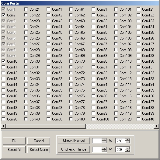
Add Com Port Dialog
Select any free port from the above dialog and click the OK button. You will now see this port added to the listing on the main screen. Click on the new port to display the settings.
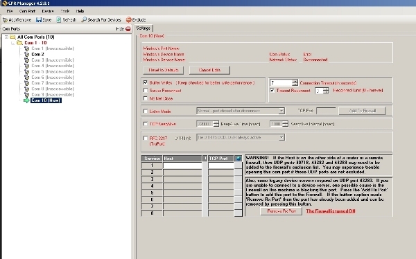
New Port Settings
Only two settings need to be in place to tell the software to map this port to the WiFi Servo Controller. In the host section enter the IP address that was assigned to your WiFi Servo Controller. In the TCP Port field enter 10002. This setting defines what port on the output end (WiFi Servo Controller) to use.
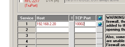
Define IP and Port
There are two ports however the primary port is always dedicated to the built in servo controller. Click save and return to the main screen. Click on the top level entry in the tree titled All Com Ports. This will display an over view of the com ports and their settings on the PC. Here you can see the current status of the port. When software has opened the port and is sending data to it you can see status change. This can be useful for setup debugging.
TCP/IP
The second method used for control of the secondary port is a direct TCP/IP connection to the IP address and port of the WiFi Servo Controller. As this is a more advanced connection method this guide will not cover the software side of this. A sample has been provided for a TCP/IP connection to the primary port. Use this as a starting point for your own software. The main advantage to using the TCP/IP connection method is that the software is stand alone and the CPR software is not needed.
Built in Java Applet
The third method for control of the secondary port is via a Java applet stored on the WiFi Servo Controller’s built in web server. Again being the most advanced connection method this guide will not cover the software side of it. A sample Java applet has been provided to connect to the primary port. Use this as a starting point for your own software. Like the TCP/IP method the advantage of this is the elimination of the CPR software as well as having to store a control program on a PC. Wherever the controller goes the control software goes too.
WiFi Servo Controller port settings
With any of the above connection methods you need to setup the port on the controller properly for use with your desired hardware. The easiest way to do this is via the web interface. Open a browser and point it to the IP address your WiFi Servo Controller was assigned. You will be prompted for a user name and password. Leave this blank and click OK. In the left hand pane you will see a link to Channel 2’s serial settings. Click this to bring up the current settings. Usually the only thing that needs to be set is the baud rate. This port is set to 9600 by default. For example say you would like to use the LinkSprite JPEG color camera with the WiFi Servo Controller. By default the camera ships with a bit rate of 38400. In order for the camera and WiFi Servo Controller to speak together this setting must be the same. Once the settings have been adjusted click OK and then on the apply settings link in the left pane. The controller will then apply the settings and then reset itself.