
How to upgrade your PCTx to v1.3 hardware
|
Version 1.0, 1.1, and 1.2 PCTx units are susceptible to damage by radios where the trainer input and output signals reside on the same line. Most often this problem comes up with Spektrum radios. If you happen to flip the switch on your radio over from trainer mode while the PCTx is connected the particular output pin on the main chip will be damaged. Usually this does not damage the PCTx fully and it will still appear to Windows and the software as connected and working; there is just no signal going into the radio.
In order to get the PCTx working again all that is needed is a replacement chip. The chip can be easily installed but it is still susceptible to damage again. Most likely this issue will happen again as it is very easy to accidentally shut off trainer mode. It's not practical to keep replacing chips so if you decide to use the same radio you may want to consider doing the following modification.
Newer PCTx's, v1.3, are protected against this. This tutorial will explain how to modify your PCTx to protect against reverse voltage damage. In order to complete the modification you will need the following parts:
- 1x 2N222 transistor
- 1x 470 OHM resistor
- 1x 2k OHM resistor
- A foot or so of wire
- A few small zip ties
- soldering Iron
- solder
To being, remove the two screws from the case of the PCTx. Clip the zip tie that holds down the cable leading to the PCTx. You can either unsolder or clip the cable leading to the radio, the choice is up to you on how you want to re-connect everything but it would be best to un-solder this part.
I won't go into detail on how to actually connect and configure the parts but the idea is to place the schematic below in between the PCTx and the output line. The only extra connection needed is a wire leading from a +5V source to the transistor collector. The easiest place to connect this line is to connect it directly to the red wire that is connected to the PCTx leading from the USB port. Here you will find four wires, only one is red. This is however the easiest place to locate but you may want to connect it to the end of the fuse for a bit more protection. The fuse is a thin yellow part about .25"x .25" in size and looks like this:
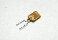
PTC fuse
Looking at the bottom of the PCTx, the 'P' and 'R' markings should be on the right hand side of the PCTx. The connection you want to make is right below this fuse on the side closest to the 'R' mark. Test this with a volt meter to make sure you have the +5v line. Once you have this line located being to assemble the schematic below.
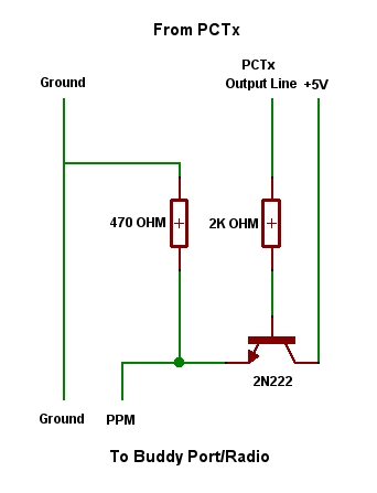
Update Schematic
Reassemble the PCTx case. Your PCTx should now be updated to the v1.3 hardware. No software updates are needed. Please be careful and perform this modification at your own risk.